
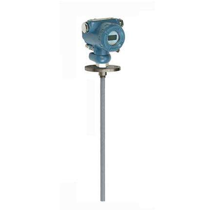
Capacitive level gauge
Description
Capacitive level gauge is suitable for continuous detection of various liquids under severe conditions such as high temperature and high pressure, strong corrosion, easy crystallization and easy plugging. Suitable for measuring sewage, acid and alkali solution, and boiler water level, the whole machine has no movable or elastic parts, impact resistance, easy installation, high reliability, high precision. It can replace the traditional float type, input type, differential pressure type and other liquid level transmitters in a variety of applications.
The core component of the capacitive liquid level meter uses the RF capacitor detection circuit to convert the standard electrical signal (generally 4~20 mA) after accurate temperature compensation and linear correction by the 16-bit MCU. HART, CANBUS, 485 communication protocols are optional for system configuration. All series of transmitters have self-calibration function, the user can automatically calibrate "zero" and "range" by two keys, to adapt to different requirements of various complex places.
The products comply with GB3836.4-2000 "Electrical Equipment in Explosive Gas environment Part 4 intrinsically safe" and GB3638.1-2000 "Electrical equipment in Explosive gas environment Part 1 General Requirements", explosion-proof mark: ExiaⅡC T6, it is suitable for zone 0, zone 1, zone 2, containing ⅱA ~ ⅱC, group T1 ~ T6 explosive gas mixture places.
Capacitive type liquid level gauge features:
1, the structure is simple, no movable or elastic components, so the reliability is very high, very little maintenance. In general, it is not necessary to carry out routine major, medium and minor maintenance.
2, a variety of signal output, convenient for different system configuration.
3, suitable for high temperature and high pressure container liquid level measurement, and the measured value is not affected by the temperature of the measured liquid, specific gravity and the shape of the container, pressure.
4, especially suitable for acid, alkali and other corrosive liquid measurement.
5, perfect overcurrent, overvoltage, power supply polarity protection.
Capacitive level meter performance:
1, detection range: 0.01~2000m
2, pressure range: -0.1MPa~32MPa
3, pole temperature resistance: -50~250℃
4. Ambient temperature: -20~60℃
5, storage temperature: -55℃ ~ +125℃
6, output signal: 4 ~ 20mA, 4 ~ 20mA overlay HART communication, 485 communication, CAN bus communication
7, power supply voltage: 12 ~ 28VDC (need to be powered by the safety grid)
8, fixing mode: screw mounting M20×1.5, M27×2,
Flange installation DN25, DN40, DN50. Special specifications can be customized on request
9, wet material: 316 stainless steel, 1Gr18Ni19Ti or PTFE
10, long-term stability: ≤0.2%FS/ year,
11, temperature drift: ≤0.02%FS/℃ (in the range of 0 ~ 70℃)
12, explosion-proof grade: intrinsic safety ExiaⅡC T6 flameproof ExdⅡC T5
13. Protection level: IP67
14, the safety parameters: Ui: 28VDC, Ii: 93mA, Pi: 0.65W, Ci: 0.042uf, Li: 0mH
Capacitance type liquid level gauge wiring:
Capacitive liquid level gauge transmitter is a standard two-wire or three-wire instrument. The power supply (signal) terminal is located at the wiring side of the instrument housing. The signal cable should be shielded wire or two twisted pair wires connected together.
Capacitive level transmitter installation and commissioning:
Cable type and rod type liquid level transmitters have a variety of mounting and fixing methods to adapt to different field conditions. When the site cannot provide M20×1.5 internal thread or flange and other process facilities, you can choose wall installation, horizontal pipe rack type and vertical pipe rack type, so that you can easily install in the field.
When measuring the medium with large fluidity, in order to prevent the sensor from swinging violently, the user can choose the counterweight accessories to stabilize the sensor. When adding the counterweight, we must put the counterweight object into the bottom of the container, so as not to pull the sensor wire.
When the site environment is harsh, the user should choose the sensor shield to protect the sensor, so as not to be damaged by foreign matter or affect the accuracy of measurement.
When using rod level transmitter, if it is not a metal container, it is necessary to connect the shell of the transmitter to the bottom of the container with a wire, otherwise the measurement is not accurate.
If the product needs to be adjusted on site, the following methods can be adopted:
B: Using intelligent circuit debugging methods:
Field zero ------ When the liquid level is at the low level of z.u, hold down the "Z" key and the "S" key for 8 seconds and release them at the same time. Press the "Z" key again to automatically adjust the output current to 4mA.
Fill up ------ When the liquid level is as high as z.u, hold down the "Z" key and the "S" key for 8 seconds and release them at the same time. Press the "S" key again to automatically adjust the output current to 20mA.
B: Using analog circuit debugging method:
When the level is at the lower limit, slowly rotate the "Z" potentiometer with a screwdriver and observe that the ammeter reads close to 4mA.
When the liquid level is at the upper limit, slowly rotate the "S" potentiometer with a screwdriver and observe that the ammeter reads closer to 20mA.
Repeat this for more than 2-3 times until the zero point and the range are accurate 4mA and 20mA respectively.
After adjustment, the cover of the transmitter should be tightened.
Message
