
Vortex flowmeter
Description
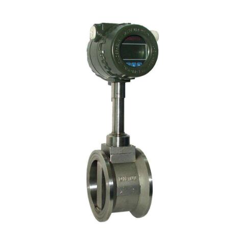
I. Product Overview:
LUGB series vortex flowmeter is mainly used for measuring the flow of medium fluid in industrial pipelines, such as gas, liquid, vapor and other media. It is characterized by small pressure loss, large range, high precision, almost unaffected by fluid density, pressure, temperature, viscosity and other parameters when measuring volume flow in working conditions. No moving mechanical parts, so high reliability, small maintenance. Instrument parameters can be stable for a long time. The instrument adopts piezoelectric stress sensor, high reliability, can work in the range of -20℃ ~ +250℃ operating temperature. It has analog standard signal and digital pulse signal output. It is easy to use with computer and other digital systems. It is a kind of ideal flowmeter.
It can be seen from the above equation that the pulse frequency signal output by VSF is not affected by the changes in physical properties and components of the fluid, that is, the instrument coefficient is only related to the shape and size of the vortex generator and pipeline within a certain Reynolds number range. However, as a flow meter, mass flow rate should be detected in material balance and energy measurement. At this time, the output signal of the flow meter should monitor the volume flow rate and fluid density at the same time. The physical properties and components of the fluid have a direct impact on the flow measurement.
LUGB series vortex flowmeter is a new type flowmeter for measuring fluid flow in closed pipeline based on Karman vortex principle. Because of its good medium adaptability, it can directly measure the volume flow of steam, air, gas, water and liquid without temperature and pressure compensation. Equipped with temperature and pressure sensors, it can measure the volume flow of standard conditions and mass flow. It is an ideal substitute for throttling flowmeter.
In order to improve the high temperature resistance and anti-vibration performance of vortex flowmeter, our company LUG improved vortex flow sensor, because of its structure and material selection, the sensor can be used in high temperature (350℃), strong vibration (≤1g) under harsh conditions.
In practical applications, the large flow is often far below the upper limit of the instrument, with the change of load, small flow and often lower than the lower limit of the instrument, the instrument is not working in the working section, in order to solve this problem, usually used in the measuring place to reduce the diameter to improve the flow rate of the measuring place, and choose the instrument to facilitate the measurement of the instrument, However, this kind of reducing method must be rectified in a straight pipe section with a length of more than 15D between the reducing pipe and the instrument, which makes processing and installation inconvenient. LGZ rectifier with circular arc profile developed by our company has multiple functions such as rectification, increasing flow velocity and changing flow velocity distribution. Its small structure size, only 1/3 of the inner diameter of the process pipe, is integrated with vortex flowmeter. It not only does not need another straight pipe section, but also can reduce the requirements on the straight pipe section of the process pipe, so it is very convenient to install.
In order to facilitate use, the battery-powered local display vortex flowmeter adopts micro-power consumption high technology, and can run uninterrupted for more than one year by using lithium battery power supply, saving the purchase and installation cost of cable and display instrument, and can display instantaneous flow and cumulative flow on the spot. The temperature compensated single-type vortex flowmeter also has a temperature sensor that can directly measure the temperature of saturated steam and calculate the pressure to display the mass flow rate of saturated steam. A body with temperature and pressure sensor for gas flow measurement can directly measure the temperature and pressure of the gas medium, so as to display the standard volume flow of gas.
Ii. Working principle:
LUGB series vortex flowmeter is composed of vortex generator, detection probe and corresponding electronic circuit designed in the flow field. When a fluid flows through a vortex-generating body, two rows of alternating vortexes are formed on both sides of it, which is called Karman vortex street. On the basis of Karman vortex street theory, it is proposed that the frequency of Karman vortex street is proportional to the flow rate of fluid, and the relationship between frequency and flow rate is given:
f = St × V/d, where:
f vortex street frequency (Hz)
Average velocity on both sides of V vortex generator (m/s)
St Strohal coefficient
These alternating vortices form a series of alternating negative pressure, which acts on the detection probe and generates a series of alternating electrical signals. After the conversion, shaping and amplification of the preamplifier, the output pulse frequency signal (or standard signal) is proportional to the synchronization of the vortices.
Iii. Use Selection and Application:
1. In order to facilitate use, the battery powered type adopts micro-power consumption high-tech technology, and the lithium battery power supply can run uninterrupted for more than one year, saving the purchase and installation cost of cable and display instrument, and can display instantaneous flow and cumulative flow on the spot.
2, the temperature compensation body also has a temperature sensor, can directly measure the temperature of saturated steam and calculate the pressure, so as to show the mass flow of saturated steam.
3, temperature and pressure compensation a body with temperature, pressure sensor, used for gas flow measurement can directly measure the temperature and pressure of the gas medium, so as to show the volume flow of gas conditions.
4, widely used in petroleum, chemical industry, metallurgy, machinery, paper, as well as urban pipeline heating, water supply, gas and other industries of low viscosity liquid, gas, steam and other single-phase fluid process measurement and energy saving management.
Four, the main characteristics:
1, can accurately measure the flow of gas, liquid and steam in a wide flow range without being affected by the physical properties of the fluid;
2, not affected by temperature and pressure, at the same time is not easy to plug, not easy to card, not easy to scale, high temperature resistance, high pressure;
3, safe and explosion-proof, suitable for harsh environment;
4, no moving parts, no holes and gaps design, product no wear, dirt resistance, no mechanical maintenance, long service life;
5, the use of micro power consumption high-tech, battery powered field display flowmeter, can not run for more than two years without power;
6. Integrated design of temperature and pressure compensation;
7, the current output is electric isolation type, with good common mode interference suppression ability;
8. Display the flow value and cumulative flow value at the same time, without switching in turn;
9, the use of anti-vibration probe, effectively eliminate the impact of external vibration;
10, adopt split type signal converter, cable length 100 meters;
11, measuring range width of 20:1;
12, the overall structure of the instrument is reasonable, the dynamic measurement range is wide, the pressure loss is small;
13, the body is made of stainless steel, which is suitable for the measurement of corrosive media;
14, the scene LCD display, pulse, 4 ~ 20mA output or 485 communication, can be connected with industrial automation system.
V. Technical parameters:
1, measuring medium: gas, liquid, vapor;
2, connection mode: flange clamping type, flange type, insert type;
3. Caliber specifications flange clamping type caliber selection of 25,32,50,80,100;
4, flange connection type caliber selection of 100,150,200;
5. Flow range (see flow range table)
6. Reynolds number of normal measured flow velocity range is 1.5×10⁴ ~ 4×10⁶; Gas 5 ~ 50m/s; Liquid 0.5 ~ 7m/s;
7. Measuring accuracy 1.0 and 1.5;
8, the measured medium temperature: normal temperature -- 25℃ ~ 100℃, high temperature -- 25℃ ~ 150℃ -25℃ ~ 250℃;
9, output signal pulse voltage output signal high level 8 ~ 10V low level 0.7 ~ 1.3V;
10. Pulse duty cycle is about 50%, transmission distance is 100m;
11, pulse current remote transmission signal 4 ~ 20 mA, transmission distance is 1000m;
12, instrument use environment temperature :-25℃ ~ +55℃ humidity :5 ~ 90% RH50℃;
13, material stainless steel, aluminum alloy;
14, power DC24V or lithium battery 3.6V;
15, explosion-proof grade iaIIbT3-T6, protection grade IP65.
Vi. Installation requirements:
1, vortex street can only be measured in one direction, pay attention to ensure that the medium flow direction is consistent with the direction shown by the arrow of the flowmeter during installation.
2, installation mode for vertical installation, medium bottom-up through the flow meter. That is, the flowmeter is mounted on a vertical pipe and the flow direction is bottom-up.
3, horizontal installation, the flowmeter must be installed in the high pressure area of the whole system, and ensure the corresponding outlet pressure; Do not install in the highest point of the pipeline, because the highest point often gas accumulation, pipeline is not full, outlet can not be directly empty.
4, when measuring high temperature fluid, try to use vertical installation; If it has to be installed horizontally, please put the transmitter part of the flowmeter vertically downward, or horizontally side mounted to avoid high temperature; Note that the installation position has good air flow or ventilation.
5, straight pipe section requirements: at least ensure that the meter before 15 times the diameter, after the meter 5 times the diameter. If the meter has elbow, indented, expanded and other interference sources, it is necessary to ensure that the meter before 30-40 times the diameter of the pipe, the meter after 6 times the diameter of the pipe. Flowmeters should be installed upstream of regulating valves, pressure or temperature sensors.
6, pay attention to the installation of pipe diameter should be slightly greater than or equal to the inner diameter of the instrument.
7. When using the sealing ring, pay attention to the inner diameter of the sealing ring should be slightly greater than or equal to the inner diameter of the instrument, and the center of the sealing ring is located in the center of the pipeline.
8. When the electrical connection of the cable inlet sealing instrument is connected, attention should be paid to the sealing of the inlet hole. *** * Choose a suitable seal interface according to meter cable inlet type (M20 x 1.5; 1/2'NPT; G1/2') and install properly and tightly. There is no sealing joint, or the installation is sloppy, can not achieve the sealing effect.
Message
