
Differential pressure transmitter
Description
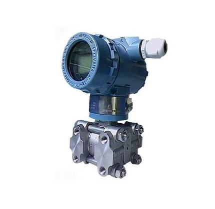
The type 1151/3351DP differential pressure transmitter is used to measure the level, density and pressure of liquid, gas or steam and then convert it into a 4 ~ 20mA DC signal output. Intelligent type can communicate with HART manual operator, through which to set, monitor or with the host unit into a field monitoring system. The 1151/3351DP field adjustable intelligent differential pressure transmitter is a new product developed by our company according to the requirements of the field. It can be separated from the manual operator and realize the field zeroing, configuration and other operations by pressing buttons. 1. Performance specifications (zero reference check range, under reference conditions, silicone oil filled with liquid, 316 L stainless steel isolation diaphragm)
1.1. Reference accuracy 1.1.1. Digital, intelligent: ±0.1% check range 1.1.2. Simulation, linearity: ±0.2% check range 1.2. Stability 1.2.1. Digital, Intelligent: 6 months, ±0.1%URL 1.2.2. Analog, linear: 6 months, ±0.2%URL 1.3. Impact of ambient temperature 1.3.1. Digital and intelligent zero point error: ±0.2%URL/56℃ Overall error: ±(0.2%URL+0.18% check range) /56℃ 1.3.2. Simulation, linear zero point error: ±0.5%URL/56℃ Overall error: ±(0.5%URL+0.5% check range)/56℃ 1.4. Static pressure effect 1.4.1. Zero point: ±0.2%URL at 13790kPa for ranges 4 to 8; Other ranges are ±0.25%URL. Zero error can be corrected online by rezeroing. 1.4.2. Range: Correctable to ±0.25% output reading /6895kPa, for range 3, correctable to ±0.5% output reading /6895kPa 1.5. At any axis, the vibration effect is ±0.05% at 200Hz. Power supply effect is less than ±0.005% output range/volt. | 1.7. Load effect: There is no load effect unless the supply voltage changes. 1.8. Electromagnetic interference/radio frequency interference (EMI/RFI influence) from 20 to 1000MHz, field strength up to 30V/M, the output drift is less than ±0.1% range. 1.9. The installation position affects the zero drift to ±0.25kPa at most. All zero drift can be corrected; It has no effect on the range. Measuring range: differential pressure: 0-1.3 ~ 6890KPa static pressure: 4, 10, 14MPa 2.2. 2.2.1. Digital and intelligent: range and zero button can be adjusted on the machine, or remote adjustment with HART manual operator. 2.2.2. Simulation and linearity: range and zero point are continuously adjustable. 2.3. Zero positive and negative transfer When zero negative transfer, the lower limit of the range must be greater than or equal to -URL; For zero positive migration, the upper limit of the range must be less than or equal to +URL. The check range is greater than or equal to the small range. 2.4. Output digital, intelligent: 4 ~ 20mA DC, users can choose linear or square root output, digital process variables superimposed on 4 ~ 20mA DC signal, can be used by the host computer using HART protocol. Analog, linear: 4 ~ 20mA DC, linear with process pressure. |
◆ Selection method
1151/3351DP | Differential pressure transmitter | |||||||
code | The range is KPa | |||||||
3 | It ranges from 0 to 1.3 to 7.5 | |||||||
4 | 0-6.2 to 37.4 | |||||||
5 | 0-31.1 to 186.8 | |||||||
6 | 0-117 to 690 | |||||||
7 | The value ranges from 0 to 345 to 2068 | |||||||
8 | The value ranges from 0-1170 to 6890 | |||||||
code | output | |||||||
E | 4-20mA | |||||||
S | Intelligent type | |||||||
Code name | Structural material | |||||||
Flanges and joints | Exhaust/drain valve | Isolation diaphragm | Filling liquid | |||||
22 | 316 stainless steel | 316 stainless steel | 316 stainless steel | Silicone oil | ||||
23 | 316 stainless steel | 316 stainless steel | Hasloy C | |||||
24 | 316 stainless steel | 316 stainless steel | Monel | |||||
25 | 316 stainless steel | 316 stainless steel | tantalum | |||||
33 | Hasloy C | Hasloy C | Hasloy C | |||||
35 | Hasloy C | Hasloy C | tantalum | |||||
44 | Monel | Monel | Monel | |||||
Code name | Maximum working pressure MPa | |||||||
B- | 4 | |||||||
C- | 10 | |||||||
D- | 14 | |||||||
code | option | |||||||
M1 | 0-100% linear indicator table | |||||||
M2 | LED display meter | |||||||
M3 | LCD display meter | |||||||
B1 | Pipe fitted with bent bracket | |||||||
B2 | Plate mounted bent bracket | |||||||
B3 | Pipe mounted flat bracket | |||||||
D1 | The side drain valve is at the upper part of the pressure chamber | |||||||
D2 | The side bleed valve is under the pressure chamber | |||||||
Not note | 1/2NPT taper pipe thread connection | |||||||
C2 | T-thread M20 x 1.5 with a ball - cone connector with a diameter of 14 - welded back | |||||||
d | Flameproof type dⅡBT4 | |||||||
i | Native safety type iaⅡCT6 | |||||||
J | Flow transmitter 4-20mA square output | |||||||
s | Stainless steel triple valve set | |||||||
Message
